Here is the overview of the presented content for ATM part.
---------------------------------------
Optical Communications
Optical Communications and OSI
Advantages and Disadvantages
Different light source (LED and LASER)
Optical Fiber
Different Types of Fiber
Fiber Transmission Effects
Optical Attenuation
Optical Dispersion
Noise in Optical Transmission
Optical Networks (Operating wavelength)
SONET
Wave Division Multiplexing
Components
SONET Network
---------------------------------------
Optical Communications (OC) is any form of communicatin using light. Its very high speed but harder to implement. In OSI, OC falls in the Physical layer and there are many ad and disad to using it.
Advantages
- more resistance to attenuation, noise. thus can transmit longer distant
- high speed
- better choice to use in dangerous environment like refinery
- Large BW permits aggregation of voice, video and data
- secure because difficult to tap
Disad
- difficult to install and handle
- cost
The two different light source for optical transmission are LED and LASER. No matter which light source is being used, they all suffer from a degree of attenuation, dispersion and noise. Where attenuation loss is due to absorption and signal scattering by fiber impurities and dispersion is the distortion of signal.
SONET - Synchronous optical networking is the multiplexing protocol for transferring multiple digital bit streams.
Wednesday, November 5, 2008
3.1 Technologies for WAN and Backbone Networks - Gigabit Ethernet
Here is the overview of the presented content for Gigabit Ethernet part.
---------------------------------------
Gigabit Ethernet
Example
MAC
Frame Bursting
Media-Independent Interface
Media
AutoNegotiation
---------------------------------------
Gigabit ethernet is various technologies for transmitting Ethernet frames at a rate of a gigabit per second (1000Mbps). It uses Ethernet frame format and MAC technology. Because it uses MAC technology, when using gigabit ethernet to form subnet, delivering of data packet can be done through repeaters, hubs, bridges and switches, but not by IP routers. An IP router may interconnect several subnets.
The Media Access Control (MAC) data communication protocol sub-layer, also known as the Medium Access Control, is a sublayer of the Data Link Layer specified in the seven-layer OSI model (layer 2).
The Carrier Sense Multiple Access with Collision Detection (CSMA/CD) protocol is defined in the MAC sublayer and support collision is each collision domain.
Ethernet supports a variet of physical mdeia, like normal copper cable and high speed optical fiber and etc. This is possible because of the Media-Independent Interface (MII) below the MAC sublayer. Now in Gigabit Ethernet, MII have been enchanced and termed with Gigabit Media-Independent Interface (GMII). GMII is backward compatible with MII.
With the use of AutoNegotiation, Gigabit Ethernet can with different speed of UTP cable media (i.e: 10/100/1000). The lowest speed of all will be taken using roughly 40ms after cables are plugged in/out.
---------------------------------------
Gigabit Ethernet
Example
MAC
Frame Bursting
Media-Independent Interface
Media
AutoNegotiation
---------------------------------------
Gigabit ethernet is various technologies for transmitting Ethernet frames at a rate of a gigabit per second (1000Mbps). It uses Ethernet frame format and MAC technology. Because it uses MAC technology, when using gigabit ethernet to form subnet, delivering of data packet can be done through repeaters, hubs, bridges and switches, but not by IP routers. An IP router may interconnect several subnets.
The Media Access Control (MAC) data communication protocol sub-layer, also known as the Medium Access Control, is a sublayer of the Data Link Layer specified in the seven-layer OSI model (layer 2).
The Carrier Sense Multiple Access with Collision Detection (CSMA/CD) protocol is defined in the MAC sublayer and support collision is each collision domain.
Ethernet supports a variet of physical mdeia, like normal copper cable and high speed optical fiber and etc. This is possible because of the Media-Independent Interface (MII) below the MAC sublayer. Now in Gigabit Ethernet, MII have been enchanced and termed with Gigabit Media-Independent Interface (GMII). GMII is backward compatible with MII.
With the use of AutoNegotiation, Gigabit Ethernet can with different speed of UTP cable media (i.e: 10/100/1000). The lowest speed of all will be taken using roughly 40ms after cables are plugged in/out.
Tuesday, November 4, 2008
3.1 Technologies for WAN and Backbone Networks - ATM
Here is the overview of the presented content for ATM part.
---------------------------------------
ATM
Features
ATM Cell
Reference Model
ATM Cell Structure
For all applications
QoS Parameters
Traffic Descriptors
---------------------------------------
ATM is a technology that emphasize on QoS. It guarantees BW, delay and packet loss.
Its a connection-oriented technology, establishes a virtual circuit between the two endpoints before the actual data exchange begins. ATM is a cell relay, packet switching protocol which provides data link layer services that run over Layer 1 links (From wikipedia)
On top of voice and data that FR carries, ATM is a truely integrated services network that can carry voice, video, data and other innovative new services.
Its operating unit is fixed small size packets called cells. This enables the simpler buffer hardware, simpler scheduling and easier to buid high capacity switches. As the cell is small size, there is no much lag time to fill it up before sending and we also have less fragmentation. However, the overhead is also q.high (5B of header for every 48B of payload).
The reference model of ATM consists of 3 planes: Users, control and management planes. And 3 basic layers: ATM Adaptation Later (AAL), ATM layer and physical layer.
User plane take charge of the transferring of user data. Control plane in charge of signaling mechanism for set up, manage and release connection. And Management plane has two part. First, the layer management plane, manage of network resources like BW and buffer in different layers. Second, the plane management plane, to do the coordination of other planes.
AAL, in summery, do the conversion of different data units into blocks of 48B ATM cell, supporting different applications. Next, ATM layer will insert the 5B header to form a complete 53B ATM cell before sending out through physical layer.
----------------------------------------------------------------------
More info from: http://www.cisco.com/en/US/docs/internetworking/technology/handbook/atm.html#wp1020651
The ATM architecture uses a logical model to describe the functionality that it supports. ATM functionality corresponds to the physical layer and part of the data link layer of the OSI reference model.
The ATM reference model is composed of the following planes, which span all layers:
•Control—This plane is responsible for generating and managing signaling requests.
•User—This plane is responsible for managing the transfer of data.
•Management—This plane contains two components:
–Layer management manages layer-specific functions, such as the detection of failures and protocol problems.
–Plane management manages and coordinates functions related to the complete system.
The ATM reference model is composed of the following ATM layers:
•Physical layer—Analogous to the physical layer of the OSI reference model, the ATM physical layer manages the medium-dependent transmission.
•ATM layer—Combined with the ATM adaptation layer, the ATM layer is roughly analogous to the data link layer of the OSI reference model. The ATM layer is responsible for the simultaneous sharing of virtual circuits over a physical link (cell multiplexing) and passing cells through the ATM network (cell relay). To do this, it uses the VPI and VCI information in the header of each ATM cell.
•ATM adaptation layer (AAL)—Combined with the ATM layer, the AAL is roughly analogous to the data link layer of the OSI model. The AAL is responsible for isolating higher-layer protocols from the details of the ATM processes. The adaptation layer prepares user data for conversion into cells and segments the data into 48-byte cell payloads.
Finally, the higher layers residing above the AAL accept user data, arrange it into packets, and hand it to the AAL. Figure 27-7 illustrates the ATM reference model.
Figure 27-7 The ATM Reference Model Relates to the Lowest Two Layers of the OSI Reference Model
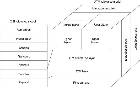
image source from www.cisco.com
----------------------------------------------------------------------
As mentioned right from the start, ATM is a technology that emphasize on QoS. It guarantees BW, delay and packet loss. Therefore, here we look at the QoS Parameters of ATM.
BW
- Peak cell rate (PCR)
- Sustained Cell Rate (SCR)
- Max Burst Size (MBS): relate to Leaky Bucket
- Min Cell rate: whats the use of this?
Delay measured using Cell transfer Delay (CTD). Its the 1 way delay from cell entering network to recieved by destination and is specified by probability density function because its never a constant.
CTD = propagation delay + processing delay + delay at multiplexer and switches + ?
---------------------------------------
ATM
Features
ATM Cell
Reference Model
ATM Cell Structure
For all applications
QoS Parameters
Traffic Descriptors
---------------------------------------
ATM is a technology that emphasize on QoS. It guarantees BW, delay and packet loss.
Its a connection-oriented technology, establishes a virtual circuit between the two endpoints before the actual data exchange begins. ATM is a cell relay, packet switching protocol which provides data link layer services that run over Layer 1 links (From wikipedia)
On top of voice and data that FR carries, ATM is a truely integrated services network that can carry voice, video, data and other innovative new services.
Its operating unit is fixed small size packets called cells. This enables the simpler buffer hardware, simpler scheduling and easier to buid high capacity switches. As the cell is small size, there is no much lag time to fill it up before sending and we also have less fragmentation. However, the overhead is also q.high (5B of header for every 48B of payload).
The reference model of ATM consists of 3 planes: Users, control and management planes. And 3 basic layers: ATM Adaptation Later (AAL), ATM layer and physical layer.
User plane take charge of the transferring of user data. Control plane in charge of signaling mechanism for set up, manage and release connection. And Management plane has two part. First, the layer management plane, manage of network resources like BW and buffer in different layers. Second, the plane management plane, to do the coordination of other planes.
AAL, in summery, do the conversion of different data units into blocks of 48B ATM cell, supporting different applications. Next, ATM layer will insert the 5B header to form a complete 53B ATM cell before sending out through physical layer.
----------------------------------------------------------------------
More info from: http://www.cisco.com/en/US/docs/internetworking/technology/handbook/atm.html#wp1020651
The ATM architecture uses a logical model to describe the functionality that it supports. ATM functionality corresponds to the physical layer and part of the data link layer of the OSI reference model.
The ATM reference model is composed of the following planes, which span all layers:
•Control—This plane is responsible for generating and managing signaling requests.
•User—This plane is responsible for managing the transfer of data.
•Management—This plane contains two components:
–Layer management manages layer-specific functions, such as the detection of failures and protocol problems.
–Plane management manages and coordinates functions related to the complete system.
The ATM reference model is composed of the following ATM layers:
•Physical layer—Analogous to the physical layer of the OSI reference model, the ATM physical layer manages the medium-dependent transmission.
•ATM layer—Combined with the ATM adaptation layer, the ATM layer is roughly analogous to the data link layer of the OSI reference model. The ATM layer is responsible for the simultaneous sharing of virtual circuits over a physical link (cell multiplexing) and passing cells through the ATM network (cell relay). To do this, it uses the VPI and VCI information in the header of each ATM cell.
•ATM adaptation layer (AAL)—Combined with the ATM layer, the AAL is roughly analogous to the data link layer of the OSI model. The AAL is responsible for isolating higher-layer protocols from the details of the ATM processes. The adaptation layer prepares user data for conversion into cells and segments the data into 48-byte cell payloads.
Finally, the higher layers residing above the AAL accept user data, arrange it into packets, and hand it to the AAL. Figure 27-7 illustrates the ATM reference model.
Figure 27-7 The ATM Reference Model Relates to the Lowest Two Layers of the OSI Reference Model
image source from www.cisco.com
----------------------------------------------------------------------
As mentioned right from the start, ATM is a technology that emphasize on QoS. It guarantees BW, delay and packet loss. Therefore, here we look at the QoS Parameters of ATM.
BW
- Peak cell rate (PCR)
- Sustained Cell Rate (SCR)
- Max Burst Size (MBS): relate to Leaky Bucket
- Min Cell rate: whats the use of this?
Delay measured using Cell transfer Delay (CTD). Its the 1 way delay from cell entering network to recieved by destination and is specified by probability density function because its never a constant.
CTD = propagation delay + processing delay + delay at multiplexer and switches + ?
3.1 Technologies for WAN and Backbone Networks - Frame Relay
Here is the overview of the presented content for Frame Relay part.
---------------------------------------
Frame Relay
Frame Relay Networks
Features
Example applications
Frame format
Frame size
Types of Virtual Circuits
---------------------------------------
First of all, Frame Relay (FR) is a technology that enables encapsulation of voice and data into packets and transport to other interconnected networks within WAN. The connection is based on Virtual Circuit which operates on packet mode (packet switching).
Special features about FR is that it is
- high speed
- low error rate
- control is done through a seperate signalling VC as data transmission
- Multiplexing and switching of VC takes place at layer 2, thus its faster and simplier
- connection based. Works like lease line // inherit from VC
- Ability to handles bursty traffic because of its high speed
- High speed access >100Mbps
There are 3 types of VC for FR
- Switched VC
- Permanent VC
- Multicast VC
- Switched VC
- A sequence of digits is dialed and the cct is established if BW is available
- cct have different DLCI (identifier) for each link from origin to destination
- DLCI is made available for reuse after a call disconnect
- Permanent VC
- Works like a lease line
- Multicast VC
- have 1 to many relationship between source and destination. When sending a packet with DLCI that is for multicast VC, router will know who to send to.
---------------------------------------
Frame Relay
Frame Relay Networks
Features
Example applications
Frame format
Frame size
Types of Virtual Circuits
---------------------------------------
First of all, Frame Relay (FR) is a technology that enables encapsulation of voice and data into packets and transport to other interconnected networks within WAN. The connection is based on Virtual Circuit which operates on packet mode (packet switching).
Special features about FR is that it is
- high speed
- low error rate
- control is done through a seperate signalling VC as data transmission
- Multiplexing and switching of VC takes place at layer 2, thus its faster and simplier
- connection based. Works like lease line // inherit from VC
- Ability to handles bursty traffic because of its high speed
- High speed access >100Mbps
There are 3 types of VC for FR
- Switched VC
- Permanent VC
- Multicast VC
- Switched VC
- A sequence of digits is dialed and the cct is established if BW is available
- cct have different DLCI (identifier) for each link from origin to destination
- DLCI is made available for reuse after a call disconnect
- Permanent VC
- Works like a lease line
- Multicast VC
- have 1 to many relationship between source and destination. When sending a packet with DLCI that is for multicast VC, router will know who to send to.
3.1 Technologies for WAN and Backbone Networks
3.1 Technologies for WAN and Backbone Networks
-----------------------------------------------
Below is the overview of chapter 3.1
WAN - Wide area Network
Backbone Networks
Frame Relay
Frame Relay Networks
Features
Example applications
Frame format
Frame size
Types of Virtual Circuits
ATM
Features
ATM Cell
Reference Model
ATM Cell Structure
For all applications
QoS Parameters
Traffic Descriptors
Gigabit Ethernet
Example
MAC
Frame Bursting
Media-Independent Interface
Media
AutoNegotiation
Optical Communications
Optical Communications and OSI
Advantages and Disadvantages
Different light source (LED and LASER)
Optical Fiber
Different Types of Fiber
Fiber Transmission Effects
Optical Attenuation
Optical Dispersion
Noise in Optical Transmission
Optical Networks (Operating wavelength)
SONET
Wave Division Multiplexing
Components
SONET Network
Subscribe to:
Comments (Atom)